Featured

Nanite All The Things – Pt2

In the last post there were a few things I wanted to follow up on with my exploration into Nanite Tessellation!

I also found the video that I meant to watch last time with Brian Karis breaking down all sorts of great things about the tech, and he touches on all the things I mentioned in the last post and more, so definitely go watch that for much cleverer insight!!

Timestamp is near the start of the Nanite Tessellation discussion, but whole video is worth watching:

Also, just after I finished the first blog post this great video talking through all sorts of Nanite things came out!

That video covers a lot of the ground of these posts also, but demonstrates them really clearly, highly recommend watching it.

Seams issues

In the last post I figured you could fix Nanite Tessellation splitting at UV seams by blending them down with vertex colours at the seam, etc!

Instead of vertex colours though, I settled on using a texture instead, wasn’t sure what sort of impact having vertex colours would have on Nanite’s clustering (when clusters LOD they have to try and maintain vertex colours, I just figured textures might be the best place to start).

To start with, I generated a new mesh for a bit of fun. Since I am now working with much lower poly meshes than before, most of the process of generation in Houdini is pretty quick, so I roughed out a new shape:

Rough shape modelled in Houdini for new rock arch

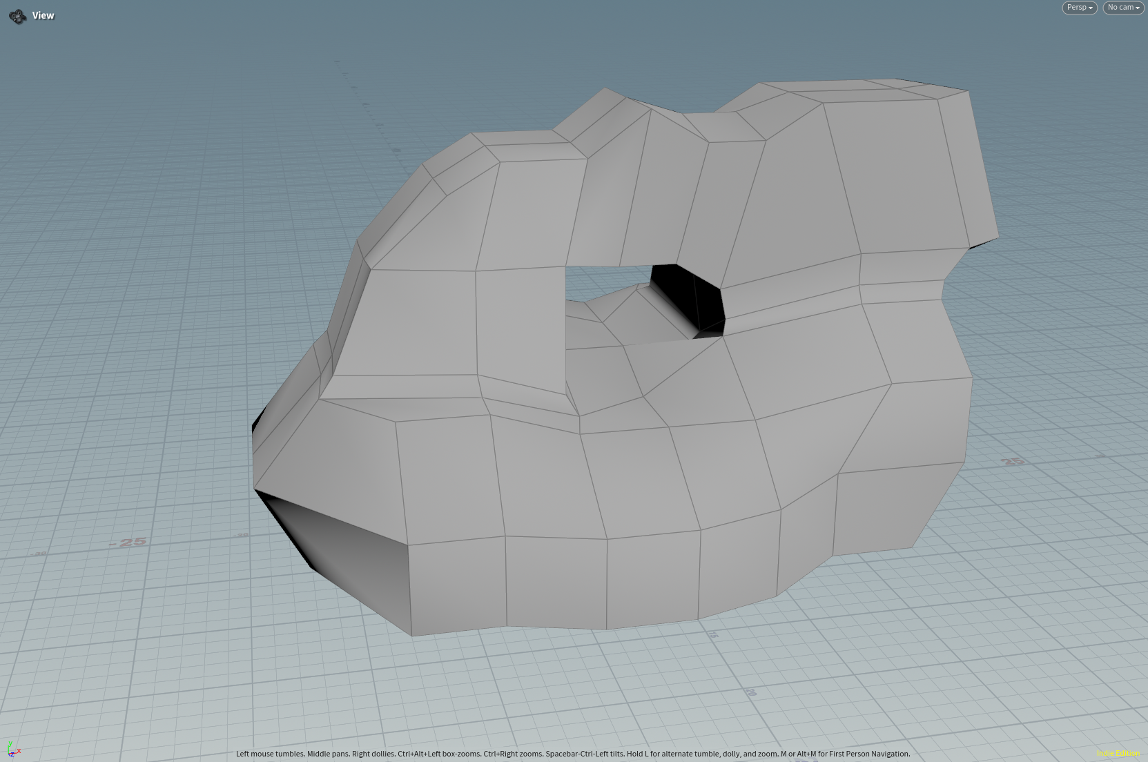
And then applied the similar noises as for the last rock, with a few tweaks:

VDB generated rock in Houdini

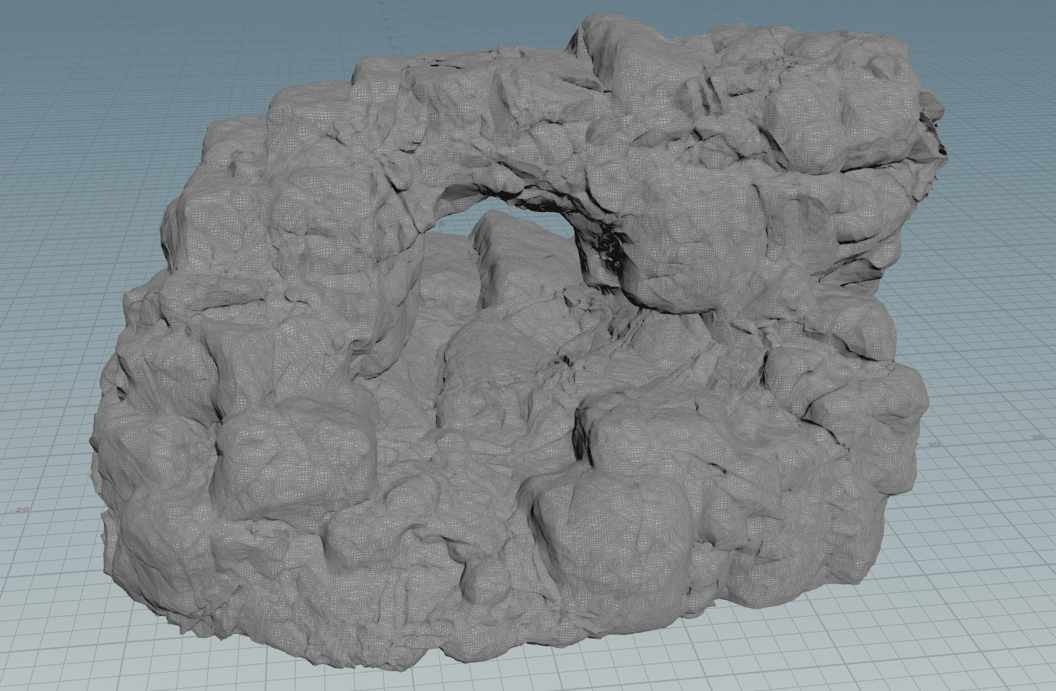
I won’t go too much into the technique here, because I think you’ll find a lot better tutorials on rock generation in Houdini out there, but my approach is mostly informed by this great training session by Rohan Dalvi:
https://www.rohandalvi.net/vdb

Tweaking the mesh and noise didn’t take too long (a few hours and hopefully reusable on other assets).
But I pushed the noise far to far with this asset and ended up with a lot of deep tunnels and cracks. It’s a bit hard to show exactly how bad it is, but if I take the camera inside the mesh you can see a problem area, which I have dozens of:

Inside a VDB rock mesh in Houdini showing a lot of internal noise that has made unwrapping it difficult

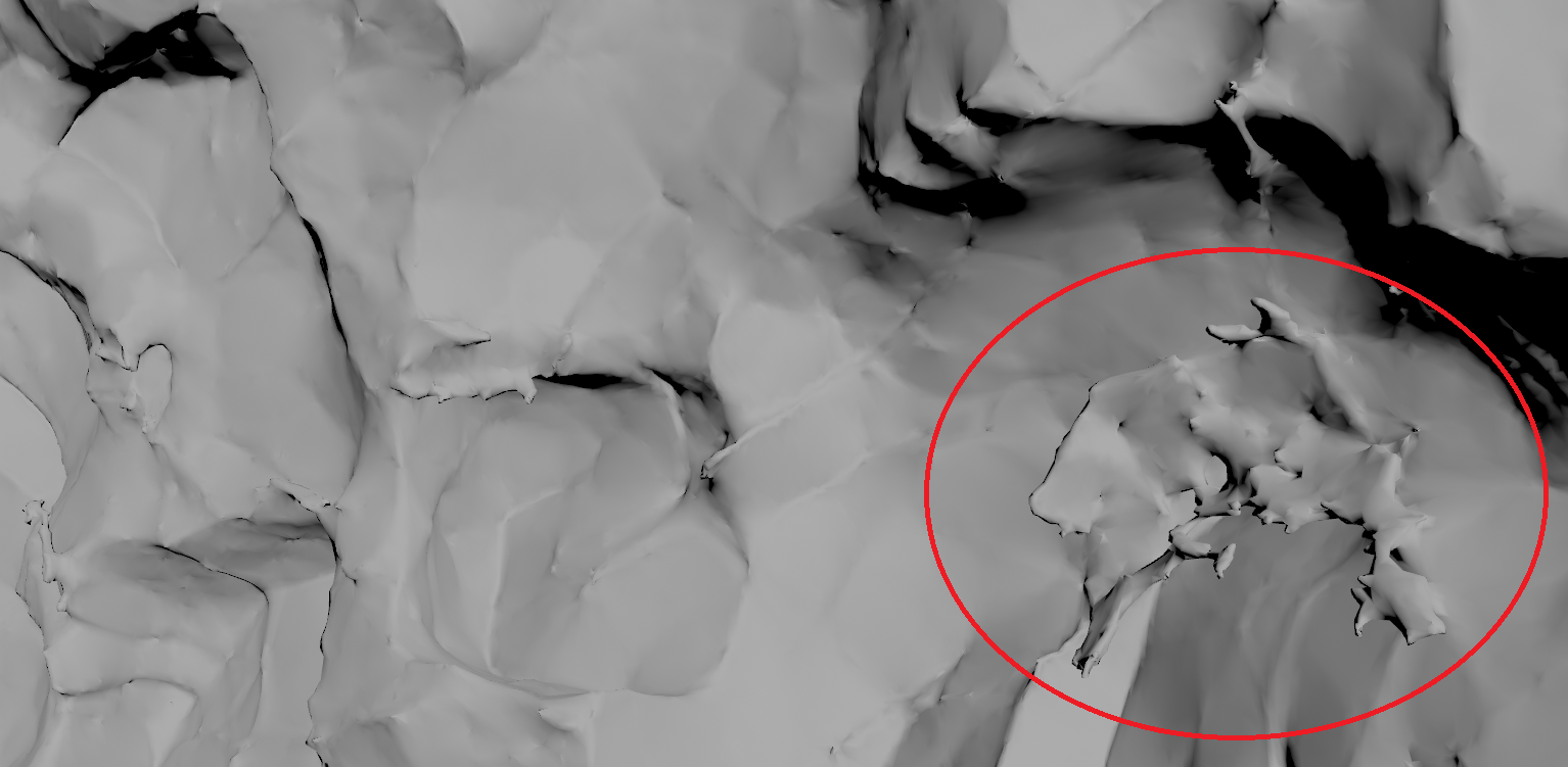
So this asset can act as an example of what not to do, because a big part of the point of me pushing Nanite Tessellation was to make unwrapping easier, and it took me probably 15 hours to select all the seams in this šŸ˜›

Cleaning up the VDB before meshing, and many other things would improve this, so I will probably come back to it.
I could also lean more into triplanar mapping in Unreal, but I don’t love relying on it, it likely gets a bit expensive when you end up with dozens of texture samples (have not profiled it recently mind you)…

So, nightmare seam selection for unwrapping:

A resmeshed VDB rock in Houdini will far too many edges selected for seams

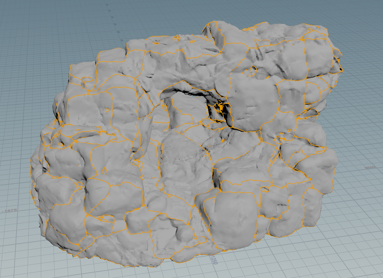
Spending a little more time on the seams is the best way I’ve found to try to avoid issues with UV layout, so I tend to end up with far more cuts than desirable, and then merge UV sheets again afterwards, otherwise you end up with a lot of overlaps and issues.

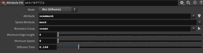
Since I already have that edge group for the seams, I can group promote it to points, and use it as an attribute for an Attribute Fill in Diffusion mode to make a mask for where the seams are:

Blur diffusion on attribute fill node in Houdini showing some of the settings I use to turn mesh seams into a wider map
Rock VDB mesh in Houdini with seams mask displayed

The Labs Map baker in “Copy Lowpoly” mode can just bake that out as a texture.

Be warned: I have found it pretty unstable, crashes 2/3 times, so make sure you save your scene and have autobackups enabled if using the Labs Baker!

Back in Unreal, I import that seams mask:

A seams mask texture imported into Unreal 5

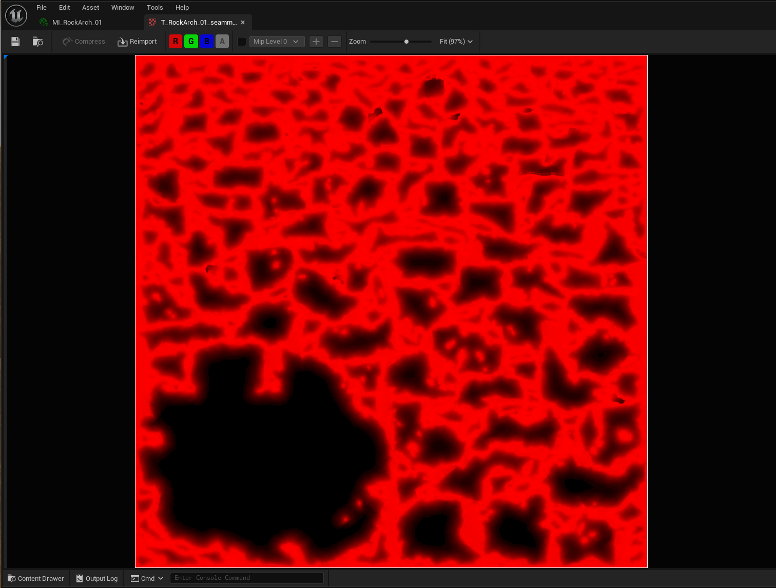
I’ll eventually pack it with other things, for now it is a lonely 1024*1024 DXT1 “Masks” type texture.
Could also give vertex data a try, but like I mentioned earlier I’m not entirely sure how much that messes with Nanite clustering.

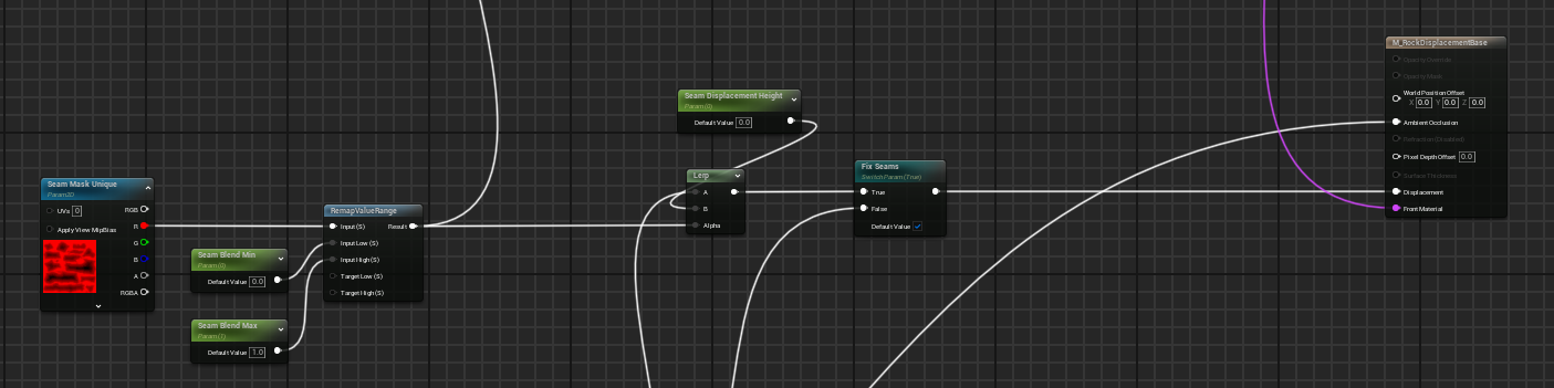
In the material I have a switch parameter that lets me preview this mask:

A material in Unreal 5 with a preview mode displaying the seams so I can tune them

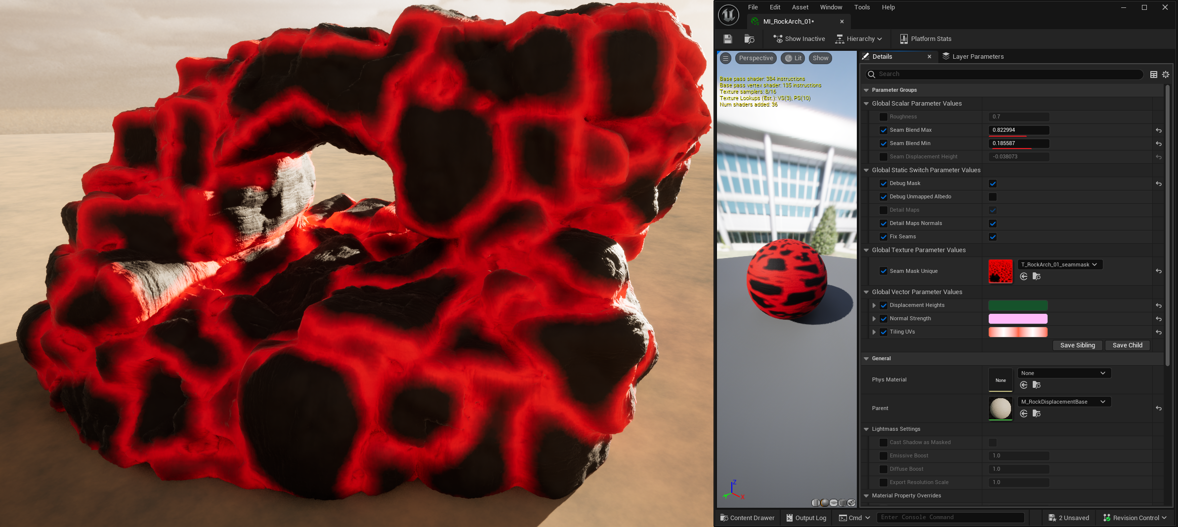
And then a min and max param so I can choose how far from the seams to blend down the displacement.
At the moment I am going quite wide with this to make sure I’m not getting displacement cracks. This is maybe necessary because my unwrap is still pretty bad, or my material needs a bit more work, but it does a good enough job for me for now!

An animated gif of the difference between masking out displacement around seams, versus having the holes in the mesh when there is no masking

Nothing too fancy in the material, just using the min and max in the input to a RemapValueRange (and since it is 0-1 output I could simplify that, but remap is nice and contained).
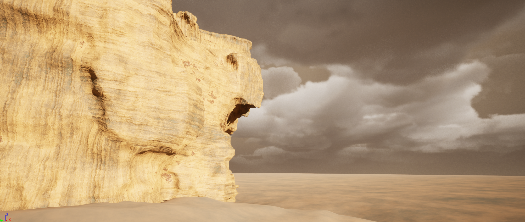
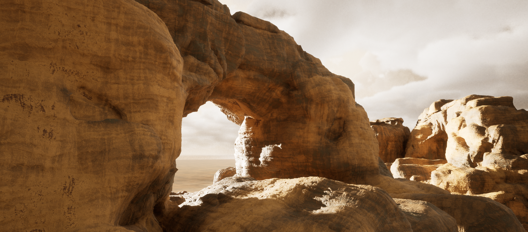
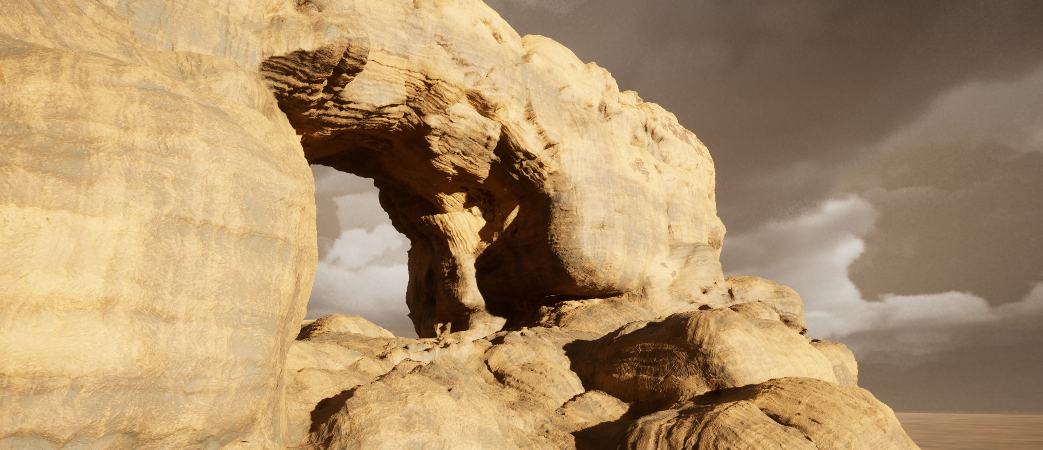
A material in Unreal remapping the seams mask into a range that works using high and low parameters

Enter Sandstone

For the time being, all detail in the material is generated from one macro mask, and three tiling normal and displacement maps.

I mentioned last time that having normal maps paired with displacement maps is unfortunately necessary because Nanite Tessellation doesn’t adjust the normals in any way.

So if it is not in a direct light, not adding to the silhouette, and you aren’t close enough to get much out of Lumen, you won’t get much at all out of Nanite Tessellation.
And that is a bit easier to show by enabling and disabling the normals:

Animated gif of detail normals on and off in Unreal to show that Nanite Tessellation doesn't modify normals in any way

I did attempt to see if I could do a ddx/ddy hacky normal generation in the material (sampling scene depth, not on the height textures I’ve generated), but for some reason couldn’t get that to work!
Might be beyond my skills, but I’d love to work out something for that in shader code instead of gross material or post process hacks.

In the long run, it would be nice to not need normals and just have heightmaps, because heightmaps are just so much simpler to work with inside materials. But for now I’d recommend just always using both together.

These are the three tiling height maps:

3 detail height maps for tiling displacement

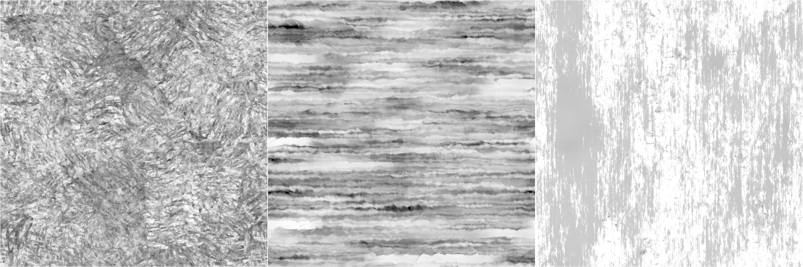
The only one I like at the moment is the middle one, so I will be remaking these!
The one on the right is particularly bad. But they were an ok starting point for setting up blending the 3 tiling textures.

I’ve always been a fan of driving albedo values with ramps, for example painting flames in Photoshop using Gradient Maps back in the day:

Gradient map in Photoshop used to remap a greyscale image to a colour ramp that makes it look like fire

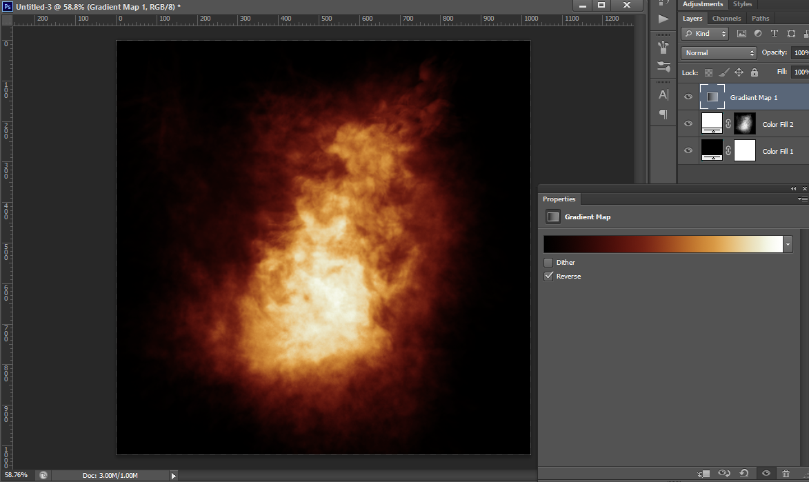
The rock material currently works in a similar way!
It maps the greyscale heights of the tiling maps to a Curve in Unreal. To start with I sampled colours from a sandstone megascans asset that I left in my scene for a point of comparison, but and some point I accidentally deleted the base Megascans material, so now they are broken forever I guess šŸ˜›

Anyway, the curve looks like this:

I have a base Macro mask baked out of Houdini with some noise and AO driving it, it is a combination of regular AO and Peaks using the Labs Ambient Occlusion nodes:

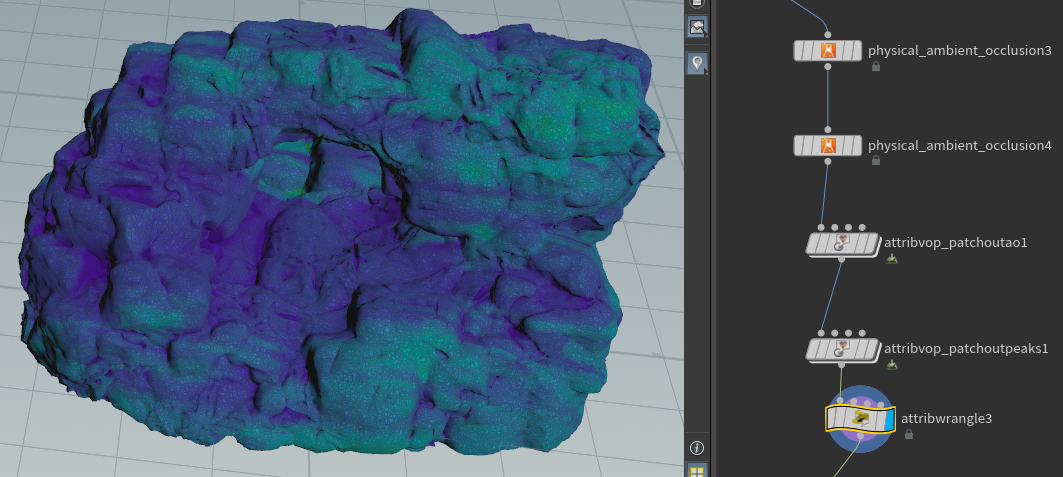
The VOPs there are used to multiply some noise through the Peaks and AO, and then I’m combining them in attribwrangle3 that I was too lazy to rename…

The mask for the arch ends up looking like this:

Macro diffuse mask baked out from Houdini that is a combination of AO and curvature

For each new rock I find some balance of the Macro + Detail1,2 & 3 heights and then use that value to look up the colour in the colour curve:

Animated gif showing the effect of 4 different maps that being used to look up a colour ramp in Unreal

All the detail maps have been packed into a float4 off this screenshot, so that is what is getting multiplied against the “Detail Height Colour Contribution” then I combine that with the Macro mask:

A Macro diffuse mask in an Unreal 5 material being used to look up a colour curve, combined with other tiling masks

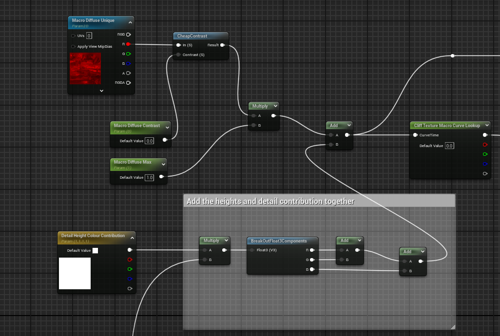
I’ll probably add in a full colour albedo texture to overlay with this just to give myself a bit more control, or perhaps a seperate macro mask driving a different curve just to get a bit more variation, but I am happy with where they are at for the moment!

A group of the 4 rock meshes I have made so far

I might also need something for better up close albedo!

But I also plan to make smaller rocks to scatter, maybe some vegetation, and other layers to combine with this, so we’ll see how much of any of that I need.

The rocks are also a uniform roughness, I might be able to get reasonable results also using the tiling heights –> curve –> roughness, but it may just be more sensible to bake out tiling roughness maps with the other tiling details.

Wrapping up

I’d still like there to be some sort of built in seam fixing along the lines of what I’ve done in the material (some sort of blending of displacement to a fixed or average value at a seam).
If it could be an average of the displacement of the two vertices on the seam, then it would already look nicer than blending verts either side of a seam down to 0, or some constant value. This would be particularly true if you are animating displacement on the mesh I think.

And baking out “seams” textures are prone to issues with wrong texture settings, will cause seams to pop in and out of existance with camera changes, etc, or any situation where texture streaming or virtual textures don’t get the right mip at the right time. You could force off mips for that texture, but that’s a great way to make the material really expensive since every time you sample it per pixel you’ll be caching the whole texture I believe. All in all it feels like a bug generator.
I will try vertex colours eventually, and compare the Nanite Clustering with and without.

I am getting happy with some of the details in these now, so hopefully I can just tidy them up, do a bit more work on seams and materials, and move on!

Rock sitting on a landscape in Unreal
A bunch of different large rock structures with a big rock arch in Unreal 5
A rock arch formation in Unreal 5

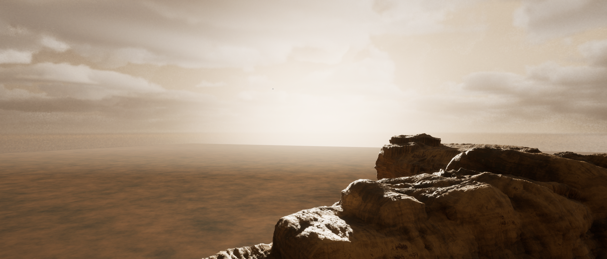
As a side note, and I could go into it in future posts, I’m generating the skydome out of Houdini 20 using some of the new skybox tools!

A wide view of some rocks and a skydome in Unreal 5. The skydome was generated using new Houdini 20 Cloud tools.

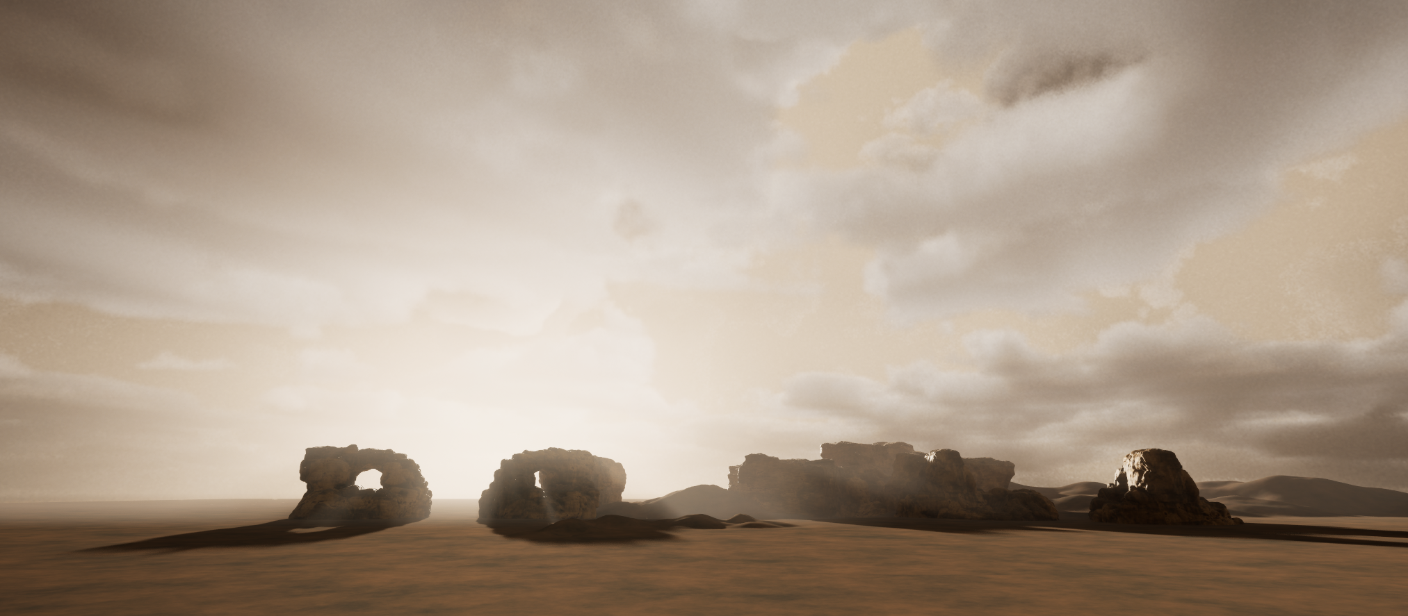
The render times are rather ridiculous though, so it’s at least half the resolution I would like, and twice as much noise as I would like, but it’ll do for now until I find a better workflow (if I render it out at 8k x 4k it will take about 60 hours, so it is currently 4k x 2k).

Building skydomes out of a bunch of overlapping card elements that can be higher quality, animated, etc, is probably a better way to go, and I’ve wanted to try that out for a while but… Very lazy.
Also thinking of using Embergen for that since it is blazingly fast!! I plan to use it for other effects in the scene eventually, just taking me a while to get to it.

So that’s about it for Nanite Tessellation, but hopefully I will have more to show in this scene in the future!
Amusingly this scene was supposed to be testing out PCG, then I got sidetracked testing out Substrate, and then Nanite Tessellation, so maybe next post will be related to the thing I was *supposed* to be doing here šŸ™‚

Nanite All The Things

A whole lot has changed in Unreal in the last few years, I’ve found it interesting to look back over all the things I wanted in the software, and how rapidly it has been advancing.

My obsession with wanting real time edge weighted subdivision surfaces in the engine, for example, has backed off substancially thanks to Nanite!

Nanite does an incredible job of compressing assets, especially if you use Trim Relative Error even a little.
For example, this little robot doodad thingo is about 560 Kb in edge weighted sub-d in Modo:

Subdivision mesh in Modo of a robot doodad, before and after subdivision

Subdivide that and import it into Unreal as Nanite, and it is about 90 Mb, but trim relative error takes it down to 5mb, with minimal visual difference:

A Nanite model in Unreal 5 before and after tweaking Trim Relative Error, which takes the size of the mesh from 100 Mb down to 5Mb

That mesh is still 10x as big as the sub-d Modo source file.

But whatever you ended up doing to get sub-d working in realtime, you’d be paying some non-zero memory cost for that subdivided asset, unless you are straight up raytracing the limit surface and not generating the triangles at all. And even *if* that is a feasible thing, I have no idea what other costs you’d have…

So yes fine, Nanite has incredible compression, and might get me over my realtime sub-d hangups šŸ˜›

Nanite Tessellation rocks!

In 5.4 we get Nanite Tessellation!

It has been demo’d very well in the GDC State of Unreal in the new Marvel Rise of Hydra game, the Preview is out, so I’ve had a few days playing šŸ™‚

It has also been discussed in a bunch of recent videos from Epic that I still need to get around to finding and watching, and will post in the comments at some point…

Why Tessellation? Lots of reasons, but I’ll start with one I really wanted to try out!

So imagine you want to make a 20m high rock cliff in one piece, and have enough ground level vertices for 1st person camera detail, with a vertex every 5 to 10 centimetres. Not really as sensible as building something out of smaller pieces, but not out of the realms of something I’d like to do.

What that looks like in Houdini for my big rock (box for rough human scale):

That is a 70 million vertex mesh, and maybe on the light side of things for close up details tbh…

Can you import that as Nanite? Sure, it will take a few minutes just to save the fbx file for it, it will be 4gb, and good luck if you want to UV / texture it…

Artists find sensible ways around this sort of thing: unwrap a lower poly mesh and project the high poly back onto it, use software like Rizom that handles high vertex counts, if you happen to know you will always be ground level, concentrate the vertex data there and have less up top, etc, etc.

Using the Displacement on import options on Static Meshes (that I believe Epic built out for upgrading Fortnite assets to Nanite) is also an option here.

Ignoring that though, importing a mesh this size into Unreal might take 30+ minutes, and you end up with something like this:

530 Mb mesh imported into Unreal as a Nanite mesh

531 Mb is still very impressive for that amount of data!

And entirely reducable using Trim Relative Error, but given it takes a long time to regenerate the mesh you might find yourself spending hours tweaking Trim Relative Error to find the right balance, and you will still be sacrificing detail.

Lower base mesh detail with tiling displacement

Nanite Tessellation gives us another approach that gives us lower resolution assets to work with in DCC tools like Houdini and Modo, but also the opportunity to create more generic tilable displacement that can be used across multiple assets.

Here is a lower poly version of that cliff mesh that has 2 tiling displacement maps on it, that I will eventually mix with at least one more, and will paint them in and out in different places. But for now, both blending together at different resolutions:

Animated gif of Nanite Tessellation displacement on and off

From a ground level, I’m pretty happy with the results, with a bit of work on the displacement maps I think it could look decent!

The base mesh is very reasonable (around 90k Nanite triangles when imported into Unreal)!

At the very least this can be faster iteration, but depending on how much you can re-use displacement textures, it can also be a big disk space and maybe memory saving!

I could move more details into the base mesh given how well Nanite compresses.
But while Houdini has some great UV tools, but they are pretty slow on big meshes, don’t guarantee no overlaps, and I haven’t had a lot of luck fixing that with the various tools available (will try again at some point).

So keeping this low enough that I can manually mark seams works well for me personally:

A mesh this low only took me about 20 minutes to set up seams for, which is not bad at all, and then the subsequent unwrap was pretty clean due to the lower detail, and only takes a few seconds to run the actual unwrap itself.

Not a fair comparison, but that mesh ends up being less than 2Mbs with a bit of tuning Trim Relative Error (which is vastly faster to tune on a mesh this density)!

The displacement maps are pretty rough and generated out of Substance Designer using some of the base noises:

I also generated out normals and AO, which for the time being is necessary, I’ll go into that a bit.

Initially when I turned on Nanite Tessellation I wasn’t sure it was working, because it looked like this:

But then it was obvious from the silhouette that it was working, so I wasn’t sure why I wasn’t seeing better details, and it took me a little while to work it out.

The shadows also showed it was doing *something* but it didn’t look quite right:

When you get close to the mesh, Lumen traces start giving you a bit more, and you start to see some detail, so that was another clue that it was definitely working (exaggerated displacement here):

And finally when you look at world normals it is obvious why:

Nanite Tessellation doesn’t update normals (assuming I didn’t mess something up, which is a big assumption…)

I was a bit surprised by this at first, but probably shouldn’t have been, this is also true of Displacement in Houdini if you don’t manually update normals after doing it:

I’m hoping at some point in the future there might be a feature that does *something* with normals, but in the meantime I’d recommend always pairing displacement maps with normal maps.

The other issue you may have noticed in a few of the screenshots is meshes splitting at UV seams:

I think for this reason you’re likely to see Nanite Tessellation mostly used on ground planes, or walls, or anything that can feasibly unwrap in a single UV sheet for now.

But with some better unwrapping than I’ve done, maybe marking up seams with vertex colours in Houdini and then blending the displacement down around them with some sort of falloff, and then also augmenting with a bunch of smaller rock pieces would cover them up.

You may also be able to mitigate this by using projected textures more, assuming you can live with the cost and issues that come with tri-planar or whatever other approach.

Thoughts

Super impressed with Nanite Tessellation!
I probably should have spent more time with it before this post, but I was too excited to try it out and share my thoughts, please comment if I got anything horribly wrong or if you have your own thoughts on some of my assumptions / comments!

I think it’s going to be a really big deal for a lot of teams, and potentially a massive production cost savings. Building a library of great tiling detail displacement maps could really speed up iteration for certain types of assets.

On top of that, I haven’t even started looking at options for animating them!
There is likely all sorts of very fun things you can do with animated displacement maps in Nanite, can’t wait to see what clever artists do with it šŸ™‚

Modo 10 on the move

A month ago, I had a fun adventure taking a train across Canada (which I can highly recommend, by the way).

I’ve moved from Toronto to Vancouver, so I’ve been sans PC for a few months.

Never fear, though, I could still run Modo on my trusty Surface Pro 1Ā šŸ™‚

TrainModo2

One of the stops along the way was in Winnipeg.
I had two tasks while there, getting some t-shirts, and finding something to model in ModoĀ (well ok, three, if you include a milkshake at VJ’s).

I decided on this auto-sprinkler thing:

PhotoRef

The plan was to do most of the modelling work with standard Pixar sub-d stuff in Modo 901 while on the train.

After I arrived in Vancouver, though, I upgraded to Modo 10, which gave me some fun new tools to play with!

Procedural Text

Non destructive modelling along the lines of Max’s stack, and/or Maya’s history is something that has been discussed a long time in Modo circles, and it has landed in Modo 10!

So, once the main mesh was finished, I could select an edge loop in the sub-d mesh, use Edges to Curves to create a curve to place the text around.

Then, in a new procedural text item, I reference in the curve, and use it with a Path generator and a path segment generator to wrap the text around the sprinkler base plate:

TextProcedural

I couldn’t work out a procedural way to get those letters rotated correctly, so I just fixed that up manually afterwards.

Fusey fuse

Since I wanted the text to be extruded from the surface and to look like it is all one piece, I decided to use Modo’s Mesh Fusion to Boolean the text on:

FoundryFusion

Since the mesh was a sub-d mesh, I didn’t really need to make a low poly, I just used the cage.
Well… Technically I should probably still make a low poly (the cage is 3500 vertices, which is pretty heavy), but it’s amazing what you can get away with these days, and soon we will have edge weighted sub-d in all major engines anyway (we won’t… But if I say it enough times, maybe it will happen??):

LowPoly.png

At this point, I unwrapped the cage, to get the thing ready for texturing.

Substance Painter time

I won’t go too much into the process here, because my approach is generally along the lines of: stack up dozens of procedural layers, and mess about with numbers for a few hours…

Since I could not be bothered rendering out a Surface ID map from Modo, I quickly created some base folders with masks created from the UV Chunk Fill mode in the Polygon Fill tool.

So in about 10 minutes I had a base set of folders to work with, and some materials applied:

UnwrapDone.png

Hello weird bronze liney thing.
Looks like someone forgot to generate world space normal maps…

Anyway, I went with a fairly standard corroded bronze material for the main body, and tweaked it a little.
Then added a bunch more procedural layers, occasionally adding paint masks to break them up here and there when I didn’t feel like adding too many more procedural controls.

There’s about 30 layers all in all, some on pretty low opacity:

SubstanceLayers.png

And here’s what I ended up with in Painter:

SubstancePassDone

Pretty happy with that šŸ™‚
Could do with some more saturation variation on the pink bits, and the dirt and wear is a bit heavy, but near enough is good enough!

Giant hover sprinkler of doom

And here it is in UE4, really large, and floating in the air, and with a lower resolution texture on it (because 2048 is super greedy :P):

UE4

Speaking of UE4: Modo 10 has materials that are compatible with the base materials in Unreal and Unity now, so you can have assets look almost identical between the two bits of software.

Which is pretty neat. I haven’t played with that feature, but I feel like it will be particularly nice for game artists who want to take Unreal assets into Modo, and render them out for folio pieces, etc.

Factory ā€“ pt 3 (early optimisation is something something)

Part 3 of https://geofflester.wordpress.com/2016/02/07/factory-pt-1/

Optimizing art early, before you have a good sense of where the actual expense of rendering your scene is, can be a pretty bad idea.

So let’s do it!!

Wut

Chill.
I’ll do it #procedurally.
Sort of.

20 gallons of evil per pixel

My ground shader isĀ pretty expensive. It’s blending all sorts of things together, currently, and I still have things to add to it.

I don’t want to optimize the actual material yet, because it’s not done, but it looks like this and invokes shame:

WetGroundMaterial.png

As a side note here, this material networkĀ looks a bit like the Utah teapot, which is unintentionally awesome.

Every pixel on this material is calculating water and dirtĀ blending.

But many of those pixels have no water or dirt on them:

NonBlendingAreas.png

So why pay the cost for all of that blending across the whole ground plane?
What can I do about it?

Probably use something like the built in UE4 terrain, you fool

Is probably what you were thinking.
I’m sure that UE4 does some nice optimization for areas of terrain that are using differing numbers of layers, etc.

So you’ve caught me out: The technique I’m going to show off here, IĀ also want to use on the walls of my factory, I just haven’t built that content yet, and I thought the ground plane would be fun to test on šŸ™‚

Back to basics

First up, I want to see exactly how much all of the fancy blending is costing.

So I made a version of the material that doesn’t do the water or the dirt, ran the level and profiled them side by side:

BlendVsNot.png

^ Simple version of my material vs the water and dirt blending one.

GPUProfile

So, you can see above that the material that has no dirt/water blending is 1.6 milliseconds cheaper.

Now, ifĀ I can put that material on the areas that don’t need the blending, I can’t expect to get that full 1.6 milliseconds back, but I might get 1 millisecond back.

That might not sound like much, but for a 60 fps game, that’s about 1/16th of the entire scene time.

Every little bit helps, getting that time back from cutting contentĀ alone can take many hours šŸ™‚

Splitting the mesh

To put my cheap material onto the non-blending sections, I’ll split the mesh around the areas where the vertex colour masks have a value of 0.

Luckily, the ground plane is subdivided quite highly so that it plays nice with UE4 tessellation and my vertex painting, so I don’t need to do anything fancy with the mesh.

Back to Houdini we go!

PolySplit.png

So, anything that has > 0 sum vertex colour is being lifted up in this shot, just to make it obvious where the mesh split is happening.

Here’s the network:

BlendMeshSplit.png

The new nodes start at “Attribcreate”, etc.

The basic flow is:

  • “Colour value max” is set as max(@Cd.r, @Cd.g), per point, so it will be set to some value if either dirt or water are present.
  • Two new Max and MinĀ attributes per polygon are created by promoting Colour Value max from Point –> Polygon, using Min and Max promotion methods (so if one vertex in the polygon has some dirt/water on it, the then max value will be non zero, etc)
  • The polygons are divided into three groups: Polygons that have no vertices with any blending, Polygons that have some blending, Polygons that have all verts that are 100% blending.
  • NOTE: For the purposes of this blog post, all I really care about is if the Polygon has no dirt/water or if it has some, but having the three groups described above will come in handy in a later blog post, you’ll just have to trust me šŸ™‚
  • The two groups of polygons I care about get two different materials applied to them in Houdini.
    When I export them to UE4, they maintain the split, and I can apply my cheaper material.

So, re-exported, here it is:

BothMaterials.png
Looks the same?

Great, mission successful! Or is it…

Checking the numbers

Back to the GPU profiler!

GPUProfileReveal.png

Ok, so the column on the right is with my two materials, the column in the middle is using the expensive material across the whole ground plane.

So my saving was a bit under one millisecond in this case.
For an hour or two of work that I can re-use in lots of places, I’m willing to call that a success šŸ™‚

Getting more back

Before cleaning up my shader, there’s a few more areas I can/might expand this, and some notes on where I expect to get more savings:

  • I’ll have smaller blending areas on my final ground plane (less water and dirt) and also on my walls. So the savings will be higher.
  • I might mask out displacement using vertex colours, so that I’m not paying for displacement across all of my ground plane and walls.
    The walls for flat sections not on the corner of the building and/or more than a few metres from the ground can go without displacement, probably.
  • The centre of the water puddles is all water: I can create a third material that just does the water stuff, and split the mesh an extra time.
    This means that the blending part of the material will be just the edges of the puddles, saving quite a lot more.

So all in all, I expect I can claw back a few more milliseconds in some cases in the final scene.

One final note, the ground plane is now three draw calls instead of one.
And I don’t care.
So there. šŸ™‚


Factory – pt 1

This blog post won’t mostly be about a factory, but if I title it this way, it might encourage me to finish something at home for a change šŸ˜‰

My wife had a great idea that I should re-make some of my older art assets, so I’m going to have a crack at this one, that I made for Heroes Over Europe, 8 years ago:

Factory

I was quite happy with this, back in the day. I’d had quite a lot of misses with texturing on that project. The jump from 32*32 texture sheets on a PS2 flight game to 512*512 texture sets was something that took a lot of adjusting to.

I was pretty happy with the amount of detail I managed to squeeze out of a single 512 set for this guy, although I had to do some fairly creative unwrapping to make it happen, so it wasn’t a very optimal asset for rendering!

The plan

I want to make a UE4 scene set at the base of a similar building.
The main technical goal is to learn to use Substance Painter better, and to finally get back to doing some environment art.

Paving the way in Houdini

First up, I wanted to have a go at making a tiling brick material in Substance Painter.
I’ve used it a bit on and off, in game jams, etc, but haven’t had much chance to dig into it.

Now… This is where a sensible artist would jump into a tool like ZBrush, and throw together a tiling high poly mesh.

But, in order to score decently onĀ Technical Director Buzz Word Bingo, I needed to be able to say the word Procedural at least a dozen more times this week, so…

HoudiniBricks

I made bricks #Procedurally in Houdini, huzzah!

I was originally planning to use Substance Designer,Ā which I’ve been playing around with on and off since Splinter Cell: Blacklist, butĀ I didn’t want to take the time to learn it properly right now. The next plan was Modo replicators (which are awesome), but I ran into a few issues with displacement.

MakingĀ bricks

Here is the network for making my brick variations, and I’ll explain a few of the less obvious bits of it:

BricksNetwork

It a little lame, but my brick is a subdivided block with some noise on it:

Brick.jpg

I didn’t want to wait for ages for every brick to have unique noise, so the “UniqueBrickCopy” node creates 8 unique IDs, which are passed into my Noise Attribute VOP, and used to offset the position for two of the noise nodes I’m using on vertex position, as you can see bottom leftĀ here:

NoiseVOP.jpg

So that the repetition isn’t obvious, I randomly flip theĀ Y and Z of the brick, so even if you get the same brick twice in a row, there’s less chance of a repeat (that’s what the random_y_180 and random_z_180 nodes are at the start of this section).

Under those flipping nodes, there are some other nodes for random rotations, scale and transform to give some variation.

Randomness

Each position in my larger tiling pattern has a unique ID, so that I can apply the same ID to two different brick placements, and know that I’m going to have the exact same brick (to make sure it tiles when I bake it out).

You can see theĀ unique IDs as the random colours in the first shot of the bricks back up near the top.

You might notice (if you squint) that the top two and bottom two rows, and left two and 2nd and 3rd from the right rows have matching random colours.

Placing the bricks in a pattern

There was a fair bit of manual back and forth to get this working, so it’s not very re-usable, but I created two offset grids, copied a brick onto each point of the grid, and played around with brick scale and grid offsets until the pattern worked.

BrickPointsNetwork.jpg

So each grid creates an “orientation” attribute, which is what rotates the bricks for the alternating rows. I merge the points together, sort them along the X and Y axis (so the the vertex numbers go up across rows).

Now, the only interesting bit here is creating the unique instance ID I mentioned before.
Since I’ve sorted the vertices, I set the ID to be the vertex ID, but I want to make sure that the last two columns and the last two rows match with the first and last columns and rows.

This is where the two wrangle nodes come in: they just check if the vertex is in the last two columns, and if it is, set the ID to be back at the start of the row.

So then we have this (sorry, bit hard to read, but pretend that the point IDs on the right match those on the left):

PointIDs.jpg

And yes, in case you are wondering, this is a lot of effort for something that could be easier done in ZBrush.
I’m not in the habit of forcing things down slow procedural paths when there is no benefit in doing so, but in this case: kittens!
(I’ve got to break my own rules sometimes for the sake of fun at home :))

Painter time

Great, all of that ugly #Procedural(tm) stuff out of the way, now on to Substance Painter!

PainterBase.jpg

So I’ve brought in the high poly from Houdini, and baked it out onto a mesh, and this is my starting point.
I’m not going to break down everything I’ve done in Substance, but here are the layers:

TextureLayers.gif

All of the layers are #Procedural(tm), using the inbuilt masks and generators in Painter, which use the curvature, ambient occlusion and thickness maps that Painter generates from your high poly mesh.

The only layer that had any manual input was the black patches, because I manually picked a bunch of IDs from my Houdini ID texture bake, to get a nice distribution:

IDPicking.jpg

The only reason I picked so many manually is that Painter seems to have some issues with edge pixels in a Surface ID map, so I had to try and not pick edge bricks.
Otherwise, I could have picked a lot less, and ramped the tolerance up more.

You might notice that the material is a little dark. I still haven’t nailed getting my UE4 lighting setup to match with Substance, so that’s something I need to work on.
Luckily, it’s pretty easy to go back and lighten it up without losing any quality šŸ™‚

Testing in UE4

UE4Plane.jpg

Pretty happy with that, should look ok with some mesh variation, concrete skirting, etc!
I’ll still need to spend more time balancing brightness, etc.

For giggles, I brought in my wet material shader from this scene:

https://geofflester.wordpress.com/2015/03/22/rising-damp/

UE4PlaneWater.jpg

Not sure if I’ll be having a wet scene or not yet, but it does add some variation, so I might keep it šŸ™‚

Oh, and in case you were wondering how I generated the vertex colour mask for the water puddles… #Procedural(tm)!

HoudiniPuddles.jpg

Exported out of Houdini, a bunch of noise, etc. You get the idea šŸ™‚

Next up

Think I’ll do some vegetation scattering on the puddle plane in Houdini, bake out the distribution to vertex colours, and use it to drive some material stuff in UE4 (moss/dirt under the plants, etc).

And probably export the plants out as a few different unique models, and their positions to something that UE4 can read.

That’s the current plan, anyway šŸ™‚


Rising damp

Wet ground

Complicated materials are a per-pixel, per frame cost, so it’s not always easy to justify making them.

For example, my tiling vertex-painted metal materials:
https://geofflester.wordpress.com/2014/08/28/checkmate-checker-plate/
This could easily have just been a uniquely unwrapped 2048 tiled texture set, with the detail painted where I want it. The way I set it up allows for memory savings, and re-usability, but sacrifices performance for that.

The best justification for complex materials is for surfaces that change / react to the environment and/or gameplay, because then you don’t really have a choice but to make an expensive material šŸ™‚

I’ve been planning for a while to make some good examples of more necessary complex materials. I started out on a desert scene with swirling sands, but that didnā€™t really end up where I wanted it, so Iā€™ve gone with a slightly more standard ā€œwet groundā€ effect:

I wonā€™t go into detail on the Blueprint setup, it just increases / decreases the water level as the player stands in front of the floating red valve. There is a volume around it, and as you move in and out of the volume, the direction of water flow changes.

The water height value feeds into this material:
Itā€™s messy, but can be summarized roughly:

  • Two layers of materials for the ground texture (Iā€™m using a muddy/rocky material and a grass material), each with:
    • Normals
    • Height
    • Albedo
    • Roughness
    • Ambient Occlusion
  • Vertex colours for blending between the two layers
  • Vertex colour used for keeping some areas dryer than others, to break up the effect
  • A normal map and colour for the water surface (blended in by depth)

I know it’s not an entirely useful image, but here is the material:

MaterialAll

All of the more important bits which are in material functions a bit further down. If anyone wants to see the whole network, I’ll take the time to screenshot it properly, and stitch it all together šŸ™‚

Hereā€™s a view showing some of the areas broken up with vertex painting (the two material layers, some dry areas, etc):

GroundPattern

The two layer blending is mostly identical in setup to the checker plate material I mentioned at the top.
The only difference being the height values, which get blended together and this resulting height is the main input for the water surface (as well as for breaking up the blending, so that tall rocks stick out a bit from the vertex blend).

Modo the things until they are Modo’d

I decided to make all of the textures procedurally.
A smarter man probably would have used the Substance tools, or ZBrush, or Houdini. Or photo source for that matter.

I’m not that guy, I’m Modo guy!! šŸ˜›

GroundPattern

So I used two layers of fur to make the grass, along with a bunch of procedural noise layers.
Nothing too exciting, but here’s the shader network:

GroundPattern

The muddy rocky stuff was a rock in a replicator and a whole bunch of “flow bozo” displacement maps, because they are awesome:

GroundPattern

So yeah, I’m not going to win any amazing texture art of the year awards.
I could spend a bit more time on them, or use them as a paint-over base, but I’ve got pretty lazy with this side project now so I didn’t even bother fixing seams šŸ™‚

But, at least it gives me pretty accurate height data to play with, which is important for water-ness!

Water Level

The current water level is passed into the material, and is used to threshold the height map, to work out where the water is.
It might help to visualise this in Photoshop. So letā€™s pretend we have a height map that has a bunch of dents in it, and the dents will fill up first:

Dents

If you put a folder above it with a Threshold adjustment layer (and an invert), you can drag the threshold around to see the water level rise (black is no water, white is water):

WaterVisualisePS

This is essentially how Iā€™m controlling the water level in the material, but Iā€™m not clamping the values to give a hard edge. Iā€™ve moved this into a function, to clean up the main material graph a little:

GetWetLevel

As a side note, the first shader of mine I saw running in a game was a threshold effect like this to make oil run down the side of a plane.
It was for Heroes Over Europe, and was on one of the programmersā€™ machines, and was ousted for a better approach almost immediately. I was very grateful that she got it in game for me, up until that point I’d just been throwing shaders at 3dsMax. It set me on the path for doing quite a bit of shader work for the next few years šŸ™‚
Anywayā€¦

Youā€™ll notice Iā€™m putting out two return values here: Mask and Depth. The Depth is very similar to the mask, but does not use the falloff value, so it essentially ā€œhow far is this pixel from the current water levelā€. I use this Depth value to tint the water with a bias, so that I can have muddy puddles that are a clearer where they are shallow.
Itā€™s pretty subtle, so it may be an unnecessary complication, but hereā€™s an example making it a little more obvious:

DepthBias

The water also has a sine wave running over the height, just to give it a little bit of ebb and flow.

Refraction

Right, so, with the water height determined, I can then use the depth of the water for a fake refraction effect.
This is usually where Iā€™d pull out the BumpOffset node, but it uses height maps, and I had a Normal map handy for the water surface.
I made a simple normal based parallax function, just because Iā€™ve had good results with this for various materials (including the UI) on Ashes Cricket 2009, and various previous attempts at rivers and water effects in other games.

Although Iā€™m only using a single transparent layer, my go-to paper has always been ā€œRendering Gooey Materials with Multiple Layersā€ by Chris Oat, from Siggraph 2006, just because it has a really nice clear example for parallax offset.

So hereā€™s my parallax offset function:

ParallaxOffset

Please pretend that ā€œVector_Reflectā€ is a ā€œCustomReflectionVectorā€ node, btw.

I rolled my own vector reflection node because I didnā€™t notice CustomReflectionVector… I think I saw that it had an input of CameraVector, and that threw me off, and Iā€™ve only just realised while writing this blog post…

So the parallax function outputs distorted UVs, and these UVs are used to look up the colour textures for the grass and mud. The water normal is just scrolling in one direction, but that seems to give a good enough distortion effect.

Taking it further

So, it was fun to work on for a few days, but thereā€™s plenty of things to do to expand/improve on it visually (including getting a real artist to make the textures :P):

  • Use UE4ā€™s flow maps to make the water flow around objects.
  • Use the back buffer (or last frame) as an input to the shader for refraction. This would be necessary if you wanted to have things sink into the water a little, and be refracted.
  • Get lighting to work above and below water (lighting is done based off the water surface normal, currently). This might be fixed by the previous improvement, if I can render and light the below water layer, then render the water surface using forward rendering and distort the already lit stuff below.
    Multiple lit layers are always a bit of a pain in deferred rendering.
  • It would be really cool if I could have a dynamic texture that I could render height values into, and multiply it on top of the height in the material.
    That way, I could create dynamic ripples, splashes, impact effects, etc!
    Not really sure how Iā€™d go about that in UE4, but it would be neat.

Iā€™m not going to do any of those things, however, because I need to stop getting distracted and get back to my Half Life scene.
Hopefully more on that soon, but this has been a nice side-track šŸ™‚

Flickery lights

It’s been a while since I’ve worked on this scene, so I thought I’d ease back in by playing around with materials again!

When the big machine in the roof of my scene turns on, I wanted to turn on a bunch of lights.
Here it is!

I’m doing this with a mix of actual lights, and an animated dynamic material.

Each piece of the geometry that is lit has vertex colour data on it, and the vertex colour is used to offset the flickering (which I’ll explain a bit later).

Here’s what the vertex colours look like (I’m only using the red channel at the moment, but I might use green and blue for other data later when I want to damage the lights):

ModoVertColours

And here’s the material:

FlickerEmissiveMaterial

The stuff outside of the “Flicker” group is just regular Normals, Roughness, Metalicity, etc.
I’m not using a separate emissive texture, I’m just masking the parts of the Albedo that are glowy, and using those in the material emissive slot. The mask is stored in the Albedo alpha channel.

Now, for the flickering part…

I’m using a texture to determine the brightness of the flicker, each pixel representing a different light intensity at a different point in time (I stretched the image to make it obvious, but it’s actually a 256 * 1 texture):

LightFlickerPattern2

The vertex colour, that I mentioned before, is the offset into the above texture. So each light has a different offset into the flicker pattern, so they all go through the same cycle, but they start at different points in the texture.

There are parameters for the strength of the flicker, minimum and maximum emissive strength, etc.
These parameters are controlled by a dynamic material instance, so that I can play with their values in the RoofMachine blueprint, like so:

DynamicMaterialParamsBlueprint

And, finally, I just set up some curves to control these parameters over the “power up” phase, which I just played around with until I was reasonably happy:

LightPowerTimeline

And that’s about it!

I’ve also done a little tweaking of the lighting, etc, and although it’s a bit too gloomy at the moment, it hides my nasty wall material that currently looks like cheese šŸ™‚

LightTestAndWalls

Fix it in post

This weekend’s UE4 challenge was to start working on my “teleport Dr Freeman to Xen” effect.

I wanted to keep it much in the same vein as the original, so it’s a flashy greeny glowy thing šŸ™‚

Telegreen

I’ll probably need to do more work on it at some point. It’s pretty weighty, sitting at 94 shader instructions and 4 texture samples (including the colour buffer). Having just screenshot the thing, there’s at least a few places with redundant nodes to clean up šŸ™‚

I can probably also remove the colour buffer and a bunch of instructions, I had planned to run distortion over it, but the effect is pretty quick, so I’m not sure it really needs it.

Here’s a screenshot of the Blueprint (I know, the resolution isn’t great):

UE4 teleport post fx

A quick breakdown:

  • “Distance from Centre” group gets the pixel’s UV position relative to the middle of the screen
  • “Ring bounds” these are the two dynamic properties that control the width of the ring that expands out from the centre.
  • “Is Pixel In Ring” is more or less like a big switch statement saying “if we’re outside the ring, do this… In the ring part, do this… In the centre of the ring, do this… Etc. I don’t use branches though, I just generate out mask values and use those in a big stack of lerps šŸ™‚
  • “Overlay Texture Value” this is where most of the work happens. I use the “ScreenAlignedPixelToPixelUVs” to sample two textures with the correct aspect ratio, then I create two copies of the UV values rotating in different directions (from the centre of the screen). I have a noisy web-like texture that gets masked by the Ring part generated in the last group, and a more general noisey texture that looks a bit like frosted glass, which blends in from the centre of the ring. At this point, we’re talking greyscale images for all these things, btw, which leads into…
  • “Mix masks…” in this group, I mix the background (colour buffer) with a black circle that expands out of the centre of the screen. I think I could probably just use alpha to blend to the background instead, since I’m not taking advantage of distorting the background (like I mentioned before). The other thing that happens in this group is I add colour to my textures, using a 256 * 1 lookup texture, so I can move the values between various shades of green before going to white. Pretty much a “Gradient Map” from Photoshop šŸ™‚

    And that’s about it! There’s some other bits and pieces in there, but nothing too exciting.
    If you’re curious about the textures, I made them in World Machine šŸ™‚ I will probably change them quite a bit over the course of the project.

    This was a good fun crash course in my first UE4 material (with dynamic properties), first full screen effect, and post-processing volumes, etc.
    I’ll probably to another post process effect when the good doctor recovers on Xen, but we’ll see!

    Previous related updates:

    Not a leg to stand on
    Bevels and Blueprints
    Chamber update #2
    Resonance cascade